AY38910 controlled by Arduino
Basic Kickstart
** This is a work in progress!!!
The whoe idea of this project, is to make a mini sythn based on this chip, the following is the schematics of all the connections. I used a TTL Crystal Oscillator of 2Mhz to provide the needed clock of the chip, and a 595 to reduce the number of the DATA pins needed for the registry address and data input to generate sounds/envelopes/noise etc.
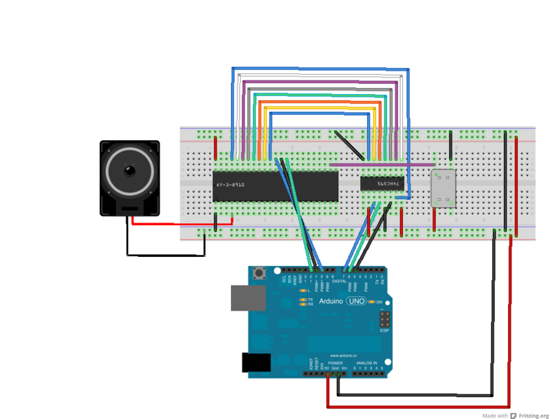
Please note that the direction of each component, the 595 is fliped for a more easy connection between the AY38910 databuse an its shifted data outs!
Here some code to test that works, it has a a song played thru an array, then a "loop" with some arps like sounds, and finally some noise sounds.
//YM38910

////Pin connected to Data in (DS) of 74HC595
const int dataPin = 5;
//Pin connected to latch pin (ST_CP) of 74HC595
const int latchPin = 6;
//Pin connected to clock pin (SH_CP) of 74HC595
const int clockPin = 7;


const int pinBC1 =  10;
const int pinBC2 =  11;
const int pinBCDIR =  12;


int tp[] = {//MIDI note number
  15289, 14431, 13621, 12856, 12135, 11454, 10811, 10204,//0-o7
  9631, 9091, 8581, 8099, 7645, 7215, 6810, 6428,//8-15
  6067, 5727, 5405, 5102, 4816, 4545, 4290, 4050,//16-23
  3822, 3608, 3405, 3214, 3034, 2863, 2703, 2551,//24-31
  2408, 2273, 2145, 2025, 1911, 1804, 1703, 1607,//32-39
  1517, 1432, 1351, 1276, 1204, 1136, 1073, 1012,//40-47
  956, 902, 851, 804, 758, 716, 676, 638,//48-55
  602, 568, 536, 506, 478, 451, 426, 402,//56-63
  379, 358, 338, 319, 301, 284, 268, 253,//64-71
  239, 225, 213, 201, 190, 179, 169, 159,//72-79
  150, 142, 134, 127, 119, 113, 106, 100,//80-87
  95, 89, 84, 80, 75, 71, 67, 63,//88-95
  60, 56, 53, 50, 47, 45, 42, 40,//96-103
  38, 36, 34, 32, 30, 28, 27, 25,//104-111
  24, 22, 21, 20, 19, 18, 17, 16,//112-119
  15, 14, 13, 13, 12, 11, 11, 10,//120-127
  0//off
};

int song[][2] ={
{60,500},
{62,500},
{64,500},
{65,500},
{64,500},
{62,500},
{60,500},
{128,500},
{64,500},
{65,500},
{67,500},
{69,500},
{67,500},
{65,500},
{64,500},
{128,500},
{60,500},
{128,500},
{60,500},
{128,500},
{60,500},
{128,500},
{60,500},
{128,500},
{60,128},
{128,128},
{60,128},
{128,128},
{62,128},
{128,128},
{62,128},
{128,128},
{64,128},
{128,128},
{64,128},
{128,128},
{65,128},
{128,128},
{65,128},
{128,128},
{64,250},
{128,250},
{62,250},
{128,250},
{60,250},
{128,1000}
};


void setup(){


    //init pins
    pinMode(latchPin, OUTPUT);
    pinMode(dataPin, OUTPUT);
    pinMode(clockPin, OUTPUT);


    pinMode(pinBC1, OUTPUT);
    pinMode(pinBC2, OUTPUT);
    pinMode(pinBCDIR, OUTPUT);

    // initialize the LED pin as an output:

    // initialize the pushbutton pin as an input:

    write_data(0x06, 0x00);
    write_data(0x07, 0x3e);
    write_data(0x08, 0x0f);
}

void set_chA(int i)
{
  write_data(0x00, tp[i]&0xff);
  write_data(0x01, (tp[i] >> 8)&0x0f);
}

void set_chB(int i)
{
  write_data(0x02, tp[i]&0xff);
  write_data(0x03, (tp[i] >> 8)&0x0f);
}

void mode_latch(){
    digitalWrite(pinBC1, HIGH);
    digitalWrite(pinBC2, HIGH);
    digitalWrite(pinBCDIR, HIGH);
}

void mode_write(){
    digitalWrite(pinBC1, LOW);
    digitalWrite(pinBC2, HIGH);
    digitalWrite(pinBCDIR, HIGH);
}

void mode_inactive(){
    digitalWrite(pinBC1, LOW);
    digitalWrite(pinBC2, LOW);
    digitalWrite(pinBCDIR, LOW);
}

void write_data(unsigned char address, unsigned char data)
{
  mode_inactive();
  //write address

  digitalWrite(latchPin, LOW);
  // shift out the bits:
  shiftOut(dataPin, clockPin, MSBFIRST, address);

  //take the latch pin high so the LEDs will light up:
  digitalWrite(latchPin, HIGH);

  mode_latch();
  mode_inactive();

  //write data
  mode_write();

  digitalWrite(latchPin, LOW);
  // shift out the bits:
  shiftOut(dataPin, clockPin, MSBFIRST, data);

  //take the latch pin high so the LEDs will light up:
  digitalWrite(latchPin, HIGH);

  mode_inactive();
}

void loop() {

  //This is test song converted to array, thanks to Alan!
  /*
  for(int i=0;i< 47;i++){
     set_chA(song[i][0]);
     delay(song[i][1]);
  }

  //Another tune
 */
  for(int i=0;i<8;i++){
   set_chA(48);
   delay(100);
   set_chA(60);
   delay(100);
  }

  for(int i=0;i<4;i++){
   set_chA(53);
   delay(100);
   set_chA(65);
   delay(100);
  }

  for(int i=0;i<4;i++){
   set_chA(55);
   delay(100);
   set_chA(67);
   delay(100);
  }

/*
  //Gunshot like sound KICK
  write_data(0x06, 0x11);
  write_data(0x07, 0x07);
  write_data(0x08, 0x10);
  write_data(0x09, 0x10);
  write_data(0x0a, 0x10);
  write_data(0x0c, 0x10);
  write_data(0x0d, 0x00);
  delay(500);

  write_data(0x06, 0x00);
  write_data(0x07, 0x07);
  write_data(0x08, 0x10);
  write_data(0x09, 0x10);
  write_data(0x0a, 0x10);
  write_data(0x0c, 0x38);
  write_data(0x0d, 0x00);
  delay(500);
*/

}
Some tone channel testing on chanA + Noise testing. Here are some videos of me, playing with this kickstart setup and code:
http://www.youtube.com/watch?v=Y7U9uktXF3s
Envelope testing http://www.youtube.com/watch?v=0l6tAst5tqk
Test with pots buttons and LEDS (very important the leds :P) http://www.youtube.com/watch?v=FHx3vPoWzMQ
Credits
Most of the code came, from the example locate here: http://kalshagar.wikispaces.com/Arduino+and+a+YMZ294
Thanks a lot Alan!!