I2C bi-directional level shifter
Introduction
This page is about a bi-directional level shifter for the I2C-bus: what it is; why you need it; and when you can do without.
A level shifter shifts the voltages of the bus signals so that devices of different voltages can communicate over the bus.
This page is to collect all information (for example from the forums), and you are invited to add your own solution.
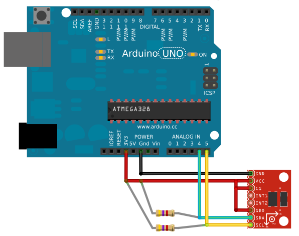
Connecting 3.3V I2C components directly to the Arduino.
A 3.3V I2C component can be connected directly to the Arduino, by using the 3.3V of the Arduino board, and using two 4k7 pull-up resistors to the 3.3V. But you have to know the risks.
Most AVR chips (the microprocessor) on the Arduino Boards run at 5 Volts, and most of those Arduino Boards have voltage regulator for 3.3 Volt. This 3.3V can be use for components that require 3.3V.
More 3.3V I2C components can be added to this bus.
Many I2C devices operate with a range of voltages. It is very well possible that all your I2C components can be used with 3.3V.
According to the datasheet of the ATmega328P a digital input should at least be 0.7 * Vcc. For +5V, the digital input must at least be 3.5V. Using the 3.3V I2C-bus for a +5V Arduino is living on the edge, and hoping that the 3.3V will be recognized as a digital high. Since the I2C-bus is rather slow, the 4k7 pull-up resistors will pull the signal fast enough to 3.3V, and with some help of the internal pull-up resistors the Arduino will work with an 3.3V I2C-bus most of the time.
The Arduino Lenoardo use the ATmega32u4. This microcontroller uses lower voltages for a valid high input. It is therefor no problem for the Arduino Leonardo to read digital signals from 3.3V components.
Even 5V I2C components can be connected to the SDA and SCL lines of the 3.3V I2C-bus. A high level will be 3.3V and not 5V, but in most cases it's enough to make it work.
Internal pull-up resistors activated by Wire libary.
The AVR microcontroller in the Arduino uses a TWI interface, which is I2C compatible. The SDA and SCL lines can be programmed with internal pull-up resistors. The Wire library of Arduino 1.0 (in 2012) enables those internal pull-up resistors with the function Wire.begin(). Those internal pull-up resistors are connected to +5V which could violate the specifications of the I2C component.
If two pull-up resistors of 4k7 to 3.3V are used, the voltage is only raised a little by the internal pull-up resistors. This is a controversial subject with many opinions, but no one has ever noticed that a chip has been damaged this way (but you do need those two 4k7 resistors).
Outside specs, (usually) works anyway
Connecting the 5V Arduino directly to a single 3.3V-powered I2C chip usually works, even though it violates official specifications in multiple ways. In practice, Arduino's internal pullups are so weak that ESD protection diodes inside the 3.3V chip limit the voltage.
(if any exceptions are discovered, where a chip is damaged or just doesn't work properly, please edit this page)
Of course, following the official I2C specification (stronger pullup resistors) and avoiding higher voltage signals at any 3.3V chip is best. Any "serious" project should follow all technical specifications.
Incompatible voltages
I2C components that use 1.8V or 2.8V can not connect directly to the Arduino. In that case a level shifter is used. Also for 3.3V I2C components is sometimes a level shifter used.
Bi-directional level shifter.
A level shifter can be used to do a voltage shift of the bi-directional signals of the I2C-bus (SDA and SCL).
This creates two groups on the I2C-bus, one group with the 5V and one group with a lower voltage. Once the level shifter is implemented, any combination of 3.3V and 5V components can be made and all within the I2C specifications.
Below is a list of possibilities:
Use two mosfets.
This is the most used one.
The Philips Applications Note AN97055 explaines it.
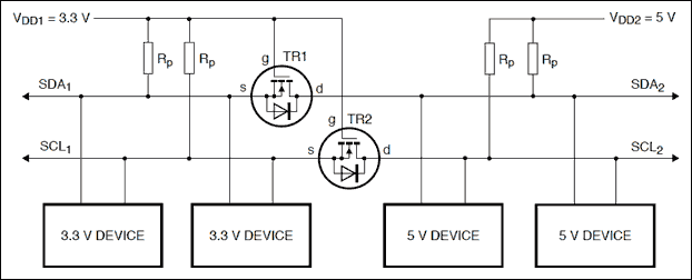
The mosfets must be types that activate with a very low gate voltage. For example mosfet BSS138 or TN2501.
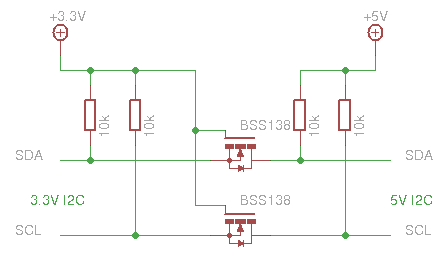
The resistors are not a part of the level shifter. They are the pull-up resistors required by the I2C bus. In this case they have to be on both sides of the level shifter.
The gates of the mosfets becomes active if either one of the signals is pulled down. The internal diode is used to make the gate active if the drain of the mosfet is pulled down. The gate is always connected to the lower voltage.
A device that pulls a line down, has to handle the current through both resistors (on the 3.3V side and on the 5V side). That's why a higher value for the pull-up resistors is choosen, mostly 10k.
Using a module.
Many common sensors are available as a module with an onboard level shifter. Sometimes those modules are specifically for the Arduino, others are more common modules for any microprocessor.
There are also modules with only the I2C level shifter.
Level shifter modules:
- The Sparkfun Logic Level Converter BOB-08745 : http://www.sparkfun.com/products/8745
It uses the BSS138 mosfet, which can be used for bus voltages as low as 1.8V. - The Sparkfun PCA9306 Level Translator Breakout : http://www.sparkfun.com/products/10403
This uses the PC9306 chip. - The Adafruit 4-channel I2C-safe Bi-directional Logic Level Converter : http://www.adafruit.com/products/757
It also uses the BSS138.
Using a level shifter IC.
There are common IC's for level shifting:
- 74HC4050
There are also special IC's for I2C level shifting:
- PCA9512
Using 4 transistors
A design idea at http://www.hagtech.com shows how to use 4 transistors. This is the document: http://www.hagtech.com/pdf/iic.pdf
The outer most resistors are pull-up resistors for the I2C bus.
A device that pulls a line down, has to pull down the current through both resistors (on the 3.3V side, and on the 5V side) and also the current through the base of the transistor. Typical values for the resistors 10k for all of them.
Interesting links
- Wikipedia about I2C: http://en.wikipedia.org/wiki/I%C2%B2C
- Extending the I2C over 5 meters: http://www.smacula.co.uk/2011/12/communicating-between-arduino-boards.html
- Level shifter at the TWI explanation: http://arduino.cc/playground/Code/ATMELTWI#shift
- A software I2C implementation, which can use any two pins of the Arduino is possible. Start with this article: http://neuroelec.com/2011/02/soft-i2c-and-programmable-i2c-address/
This way even multiple I2C busses are possible. - A i2c_scanner can be used to check if the device is connected to the i2c bus.