MPU-6050 Accelerometer + Gyro
Navigation
Introduction
The InvenSense MPU-6050 sensor contains a MEMS accelerometer and a MEMS gyro in a single chip. It is very accurate, since it contains 16-bits analog to digital conversion hardware for each channel. Therefor it captures the x, y, and z channel at the same time.
The MPU-6050 is not expensive, since it combines both an accelerometer and a gyro.
It can be easy, or not.
Reading the raw values for the accelerometer and gyro is easy. The sleep mode has to be disabled, and then the registers for the accelerometer and gyro can be read.
But the sensor also contains a 1024 byte FIFO buffer. The sensor values can be programmed to be placed in the FIFO buffer. And the buffer can be read by the Arduino.
A little more complicated is the ability to control a second I2C-device.
The MPU-6050 always acts as a slave to the Arduino with the SDA and SCL pins connected to the I2C-bus.
But beside the normal I2C-bus, it has it's own I2C controller to be a master on a second (sub)-I2C-bus. It uses the pins AUX_DA and AUX_CL for that second (sub)-I2C-bus.
It can control, for example, a magnetometer. The values of the magnetometer can be passed on to the Arduino.
Things get really complex with the "DMP".
The sensor has a "Digital Motion Processor" (DMP), also called a "Digital Motion Processing Unit". This DMP can be programmed with firmware and is able to do complex calculations with the sensor values.
For this DMP, InvenSense has a discouragement policy, by not supplying enough information how to program the DMP. However, some have used reverse engineering to capture firmware.
The DMP ("Digital Motion Processor") can do fast calculations directy on the chip. This reduces the load for the microcontroller (like the Arduino). The DMP is even able to do calculations with the sensor values of another chip, for example a magnetometer connected to the second (sub)-I2C-bus.
Information and Programs.
The accelerometer and gyro values are called the "raw" values. This is just as with other accelerometer and gyro sensors.
More sophisticated is using the DMP to retrieve specific computed values from the sensor.
The code on this page (scroll down) is just a simple and basic sketch to read the raw values.
For more serious use of the MPU-6050, Jeff Rowberg has done an excellent job.
See his I2C lib: http://www.i2cdevlib.com/devices/mpu6050
Or the latest code on github: https://github.com/jrowberg/i2cdevlib/tree/master/Arduino/MPU6050
The FreeIMU library includes the MPU-6050 code from Jeff Rowberg.
The FreeIMU library: http://www.varesano.net/projects/hardware/FreeIMU
To start with the MPU-6050, see the page of InvenSense: http://www.invensense.com/mems/gyro/mpu6050.html
For other programs and sensors, see the Degrees Of Freedom, 6DOF, 9DOF, 10DOF, 11DOF-section in the Playground index.
Breakout boards.
There are a number of "breakout boards" or "sensor boards" with the MPU-6050.
Sparkfun SEN-11028
With schematic and full information. This breakout board must be used with 3.3V. There is no voltage regulator and no I2C-level shifter on the board. The pull-up resistors for the I2C-bus are 10k. Pull-up resistors of 4k7 are preferred, so two extra 10k pull-up resistors could be added.
Drotek IMU 10DOF - MPU6050 + HMC5883 + MS5611
This sensor board contains three sensors. A schematic is not provided. The interrupt ('INT') of the MPU-6050 is not made available. Therefor the FIFO and the Jeff Rowberg library can not be used.
Drotek MPU-6050 Invensense
This breakout board contains a voltage regulator. It can be used with 3.3V and with 5V. A schematic is not provided.
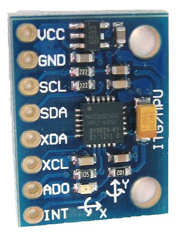
GY-521
This schematic is hard to find, so here is a copy: http://arduino.cc/playground/uploads/Main/MPU6050-V1-SCH.jpg
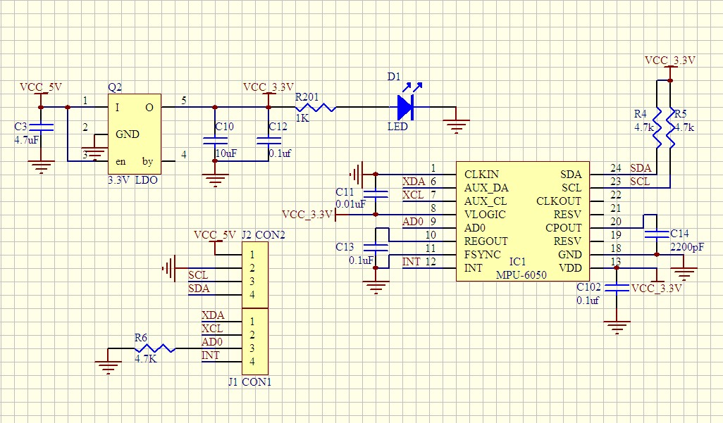
GY-52
Flyduino MPU6050 Break Out onboard 3.3V reg
This sensor board contains a voltage regulator, so it can also be used with 5V. The pull-up resistors of the I2C-bus are 4k7. It is actually a GY-52 breakout board.
Flyduino 10DOF IMU GY-86 MPU6050+HMC5883l+MS5611
A sensor board with the MPU-6050 and a magnetometer and barometer. A schematic is not provided. The sensor board contains a voltage regulator, so it can be used with 5V. There seems to be also a level shifter on the board for the I2C-bus. The pull-up resistors for the I2C-bus seems to be 2k2, which is rather low.
no name breakout board
The header is on the right with the pins in this order: "5V", "3V3", "GND", "SCL", "SDA", "INT", "SYNC", "CLK", "ASCL", "ADSA".
There are two pull-up resistors for the SCL and SDA, but the value is unknown. On the back are three solder jumpers, one of them for AD0.
Measurements.
The raw values raises questions in the forums, since the raw values might seem unstable. Below are the raw values of the sensor that I measured, so you can compare them with your own raw values.
The raw values changes a lot due to a number of reasons. The default sensitivity is high, and the sensor returnes 16 bits, but the actual valid number of bits is less than 16 bits. Since they are 16 bits, a variation of 50 is just a very small variation.
The next measurement were done in these conditions:
- The sensor was placed as horizontal as possible.
- It was placed on concreet, not a wooden table.
- During the measurements, there was no traffic in the street.
- An battery of 12V was used, not the less stable voltage from the USB bus. I used a battery instead of an adapter to avoid any mains noise.
- The circuit was on for 15 minutes, to stabalize any temperature influence.
- The room temperature was 25 degrees Celcius.
MPU-6050
Read accel, temp and gyro, error = 0
accel x,y,z: 184, -484, 14992
temperature: 29.635 degrees Celsius
gyro x,y,z : 367, 220, -812,

MPU-6050
Read accel, temp and gyro, error = 0
accel x,y,z: 116, -364, 15056
temperature: 29.635 degrees Celsius
gyro x,y,z : 373, 226, -766,

MPU-6050
Read accel, temp and gyro, error = 0
accel x,y,z: 232, -432, 15100
temperature: 29.682 degrees Celsius
gyro x,y,z : 382, 232, -790,

MPU-6050
Read accel, temp and gyro, error = 0
accel x,y,z: 280, -468, 15136
temperature: 29.635 degrees Celsius
gyro x,y,z : 368, 211, -820,

MPU-6050
Read accel, temp and gyro, error = 0
accel x,y,z: 140, -432, 15108
temperature: 29.588 degrees Celsius
gyro x,y,z : 388, 203, -806,

MPU-6050
Read accel, temp and gyro, error = 0
accel x,y,z: 220, -464, 14920
temperature: 29.541 degrees Celsius
gyro x,y,z : 374, 196, -774,

MPU-6050
Read accel, temp and gyro, error = 0
accel x,y,z: 172, -440, 15100
temperature: 29.588 degrees Celsius
gyro x,y,z : 363, 200, -769,
Sketch.
The sketch below is the code made with Arduino 1.0.1 and it uses I2C-bus communication.
The code uses the Arduino functions as much as possible. It is just a simple and basic sketch to get the MPU-6050 working.
The I2C-address depends on the AD0 pin of the sensor. If it is connected to ground, the address is 0x68. If it is connected to VLOGIC (+3.3V) it is 0x69. There are a few sensor boards with the MPU-6050 sensor already soldered on it. Some of those boards have a pull-down resistor at AD0 (address = 0x68), others have a pull-up resistor (address = 0x69).
The acceleration and gyro values of the sketch are raw values, which are not yet compensated for offset. The very first acceleration and gyro values after power up are sometimes not valid.
The sketch is about 7kbyte, and will fit in a ATmega8.
// -----------------------------
//
// By arduino.cc user "Krodal".
// June 2012
// Open Source / Public Domain
//
// Using Arduino 1.0.1
// It will not work with an older version,
// since Wire.endTransmission() uses a parameter
// to hold or release the I2C bus.
//
// Documentation:
// - The InvenSense documents:
// - "MPU-6000 and MPU-6050 Product Specification",
// PS-MPU-6000A.pdf
// - "MPU-6000 and MPU-6050 Register Map and Descriptions",
// RM-MPU-6000A.pdf or RS-MPU-6000A.pdf
// - "MPU-6000/MPU-6050 9-Axis Evaluation Board User Guide"
// AN-MPU-6000EVB.pdf
//
// The accuracy is 16-bits.
//
// Temperature sensor from -40 to +85 degrees Celsius
// 340 per degrees, -512 at 35 degrees.
//
// At power-up, all registers are zero, except these two:
// Register 0x6B (PWR_MGMT_2) = 0x40 (I read zero).
// Register 0x75 (WHO_AM_I) = 0x68.
//
#include <Wire.h>
// The name of the sensor is "MPU-6050".
// For program code, I omit the '-',
// therefor I use the name "MPU6050....".
// Register names according to the datasheet.
// According to the InvenSense document
// "MPU-6000 and MPU-6050 Register Map
// and Descriptions Revision 3.2", there are no registers
// at 0x02 ... 0x18, but according other information
// the registers in that unknown area are for gain
// and offsets.
//
#define MPU6050_AUX_VDDIO 0x01 // R/W
#define MPU6050_SMPLRT_DIV 0x19 // R/W
#define MPU6050_CONFIG 0x1A // R/W
#define MPU6050_GYRO_CONFIG 0x1B // R/W
#define MPU6050_ACCEL_CONFIG 0x1C // R/W
#define MPU6050_FF_THR 0x1D // R/W
#define MPU6050_FF_DUR 0x1E // R/W
#define MPU6050_MOT_THR 0x1F // R/W
#define MPU6050_MOT_DUR 0x20 // R/W
#define MPU6050_ZRMOT_THR 0x21 // R/W
#define MPU6050_ZRMOT_DUR 0x22 // R/W
#define MPU6050_FIFO_EN 0x23 // R/W
#define MPU6050_I2C_MST_CTRL 0x24 // R/W
#define MPU6050_I2C_SLV0_ADDR 0x25 // R/W
#define MPU6050_I2C_SLV0_REG 0x26 // R/W
#define MPU6050_I2C_SLV0_CTRL 0x27 // R/W
#define MPU6050_I2C_SLV1_ADDR 0x28 // R/W
#define MPU6050_I2C_SLV1_REG 0x29 // R/W
#define MPU6050_I2C_SLV1_CTRL 0x2A // R/W
#define MPU6050_I2C_SLV2_ADDR 0x2B // R/W
#define MPU6050_I2C_SLV2_REG 0x2C // R/W
#define MPU6050_I2C_SLV2_CTRL 0x2D // R/W
#define MPU6050_I2C_SLV3_ADDR 0x2E // R/W
#define MPU6050_I2C_SLV3_REG 0x2F // R/W
#define MPU6050_I2C_SLV3_CTRL 0x30 // R/W
#define MPU6050_I2C_SLV4_ADDR 0x31 // R/W
#define MPU6050_I2C_SLV4_REG 0x32 // R/W
#define MPU6050_I2C_SLV4_DO 0x33 // R/W
#define MPU6050_I2C_SLV4_CTRL 0x34 // R/W
#define MPU6050_I2C_SLV4_DI 0x35 // R
#define MPU6050_I2C_MST_STATUS 0x36 // R
#define MPU6050_INT_PIN_CFG 0x37 // R/W
#define MPU6050_INT_ENABLE 0x38 // R/W
#define MPU6050_INT_STATUS 0x3A // R
#define MPU6050_ACCEL_XOUT_H 0x3B // R
#define MPU6050_ACCEL_XOUT_L 0x3C // R
#define MPU6050_ACCEL_YOUT_H 0x3D // R
#define MPU6050_ACCEL_YOUT_L 0x3E // R
#define MPU6050_ACCEL_ZOUT_H 0x3F // R
#define MPU6050_ACCEL_ZOUT_L 0x40 // R
#define MPU6050_TEMP_OUT_H 0x41 // R
#define MPU6050_TEMP_OUT_L 0x42 // R
#define MPU6050_GYRO_XOUT_H 0x43 // R
#define MPU6050_GYRO_XOUT_L 0x44 // R
#define MPU6050_GYRO_YOUT_H 0x45 // R
#define MPU6050_GYRO_YOUT_L 0x46 // R
#define MPU6050_GYRO_ZOUT_H 0x47 // R
#define MPU6050_GYRO_ZOUT_L 0x48 // R
#define MPU6050_EXT_SENS_DATA_00 0x49 // R
#define MPU6050_EXT_SENS_DATA_01 0x4A // R
#define MPU6050_EXT_SENS_DATA_02 0x4B // R
#define MPU6050_EXT_SENS_DATA_03 0x4C // R
#define MPU6050_EXT_SENS_DATA_04 0x4D // R
#define MPU6050_EXT_SENS_DATA_05 0x4E // R
#define MPU6050_EXT_SENS_DATA_06 0x4F // R
#define MPU6050_EXT_SENS_DATA_07 0x50 // R
#define MPU6050_EXT_SENS_DATA_08 0x51 // R
#define MPU6050_EXT_SENS_DATA_09 0x52 // R
#define MPU6050_EXT_SENS_DATA_10 0x53 // R
#define MPU6050_EXT_SENS_DATA_11 0x54 // R
#define MPU6050_EXT_SENS_DATA_12 0x55 // R
#define MPU6050_EXT_SENS_DATA_13 0x56 // R
#define MPU6050_EXT_SENS_DATA_14 0x57 // R
#define MPU6050_EXT_SENS_DATA_15 0x58 // R
#define MPU6050_EXT_SENS_DATA_16 0x59 // R
#define MPU6050_EXT_SENS_DATA_17 0x5A // R
#define MPU6050_EXT_SENS_DATA_18 0x5B // R
#define MPU6050_EXT_SENS_DATA_19 0x5C // R
#define MPU6050_EXT_SENS_DATA_20 0x5D // R
#define MPU6050_EXT_SENS_DATA_21 0x5E // R
#define MPU6050_EXT_SENS_DATA_22 0x5F // R
#define MPU6050_EXT_SENS_DATA_23 0x60 // R
#define MPU6050_MOT_DETECT_STATUS 0x61 // R
#define MPU6050_I2C_SLV0_DO 0x63 // R/W
#define MPU6050_I2C_SLV1_DO 0x64 // R/W
#define MPU6050_I2C_SLV2_DO 0x65 // R/W
#define MPU6050_I2C_SLV3_DO 0x66 // R/W
#define MPU6050_I2C_MST_DELAY_CTRL 0x67 // R/W
#define MPU6050_SIGNAL_PATH_RESET 0x68 // R/W
#define MPU6050_MOT_DETECT_CTRL 0x69 // R/W
#define MPU6050_USER_CTRL 0x6A // R/W
#define MPU6050_PWR_MGMT_1 0x6B // R/W
#define MPU6050_PWR_MGMT_2 0x6C // R/W
#define MPU6050_FIFO_COUNTH 0x72 // R/W
#define MPU6050_FIFO_COUNTL 0x73 // R/W
#define MPU6050_FIFO_R_W 0x74 // R/W
#define MPU6050_WHO_AM_I 0x75 // R
// Defines for the bits, to be able to change
// between bit number and binary definition.
// By using the bit number, programming the sensor
// is like programming the AVR microcontroller.
// But instead of using "(1<<X)", or "_BV(X)",
// the Arduino "bit(X)" is used.
#define MPU6050_D0 0
#define MPU6050_D1 1
#define MPU6050_D2 2
#define MPU6050_D3 3
#define MPU6050_D4 4
#define MPU6050_D5 5
#define MPU6050_D6 6
#define MPU6050_D7 7
// AUX_VDDIO Register
#define MPU6050_AUX_VDDIO MPU6050_D7 // I2C high: 1=VDD, 0=VLOGIC
// CONFIG Register
// DLPF is Digital Low Pass Filter for both gyro and accelerometers.
// These are the names for the bits.
// Use these only with the bit() macro.
#define MPU6050_DLPF_CFG0 MPU6050_D0
#define MPU6050_DLPF_CFG1 MPU6050_D1
#define MPU6050_DLPF_CFG2 MPU6050_D2
#define MPU6050_EXT_SYNC_SET0 MPU6050_D3
#define MPU6050_EXT_SYNC_SET1 MPU6050_D4
#define MPU6050_EXT_SYNC_SET2 MPU6050_D5
// Combined definitions for the EXT_SYNC_SET values
#define MPU6050_EXT_SYNC_SET_0 (0)
#define MPU6050_EXT_SYNC_SET_1 (bit(MPU6050_EXT_SYNC_SET0))
#define MPU6050_EXT_SYNC_SET_2 (bit(MPU6050_EXT_SYNC_SET1))
#define MPU6050_EXT_SYNC_SET_3 (bit(MPU6050_EXT_SYNC_SET1)|bit(MPU6050_EXT_SYNC_SET0))
#define MPU6050_EXT_SYNC_SET_4 (bit(MPU6050_EXT_SYNC_SET2))
#define MPU6050_EXT_SYNC_SET_5 (bit(MPU6050_EXT_SYNC_SET2)|bit(MPU6050_EXT_SYNC_SET0))
#define MPU6050_EXT_SYNC_SET_6 (bit(MPU6050_EXT_SYNC_SET2)|bit(MPU6050_EXT_SYNC_SET1))
#define MPU6050_EXT_SYNC_SET_7 (bit(MPU6050_EXT_SYNC_SET2)|bit(MPU6050_EXT_SYNC_SET1)|bit(MPU6050_EXT_SYNC_SET0))
// Alternative names for the combined definitions.
#define MPU6050_EXT_SYNC_DISABLED MPU6050_EXT_SYNC_SET_0
#define MPU6050_EXT_SYNC_TEMP_OUT_L MPU6050_EXT_SYNC_SET_1
#define MPU6050_EXT_SYNC_GYRO_XOUT_L MPU6050_EXT_SYNC_SET_2
#define MPU6050_EXT_SYNC_GYRO_YOUT_L MPU6050_EXT_SYNC_SET_3
#define MPU6050_EXT_SYNC_GYRO_ZOUT_L MPU6050_EXT_SYNC_SET_4
#define MPU6050_EXT_SYNC_ACCEL_XOUT_L MPU6050_EXT_SYNC_SET_5
#define MPU6050_EXT_SYNC_ACCEL_YOUT_L MPU6050_EXT_SYNC_SET_6
#define MPU6050_EXT_SYNC_ACCEL_ZOUT_L MPU6050_EXT_SYNC_SET_7
// Combined definitions for the DLPF_CFG values
#define MPU6050_DLPF_CFG_0 (0)
#define MPU6050_DLPF_CFG_1 (bit(MPU6050_DLPF_CFG0))
#define MPU6050_DLPF_CFG_2 (bit(MPU6050_DLPF_CFG1))
#define MPU6050_DLPF_CFG_3 (bit(MPU6050_DLPF_CFG1)|bit(MPU6050_DLPF_CFG0))
#define MPU6050_DLPF_CFG_4 (bit(MPU6050_DLPF_CFG2))
#define MPU6050_DLPF_CFG_5 (bit(MPU6050_DLPF_CFG2)|bit(MPU6050_DLPF_CFG0))
#define MPU6050_DLPF_CFG_6 (bit(MPU6050_DLPF_CFG2)|bit(MPU6050_DLPF_CFG1))
#define MPU6050_DLPF_CFG_7 (bit(MPU6050_DLPF_CFG2)|bit(MPU6050_DLPF_CFG1)|bit(MPU6050_DLPF_CFG0))
// Alternative names for the combined definitions
// This name uses the bandwidth (Hz) for the accelometer,
// for the gyro the bandwidth is almost the same.
#define MPU6050_DLPF_260HZ MPU6050_DLPF_CFG_0
#define MPU6050_DLPF_184HZ MPU6050_DLPF_CFG_1
#define MPU6050_DLPF_94HZ MPU6050_DLPF_CFG_2
#define MPU6050_DLPF_44HZ MPU6050_DLPF_CFG_3
#define MPU6050_DLPF_21HZ MPU6050_DLPF_CFG_4
#define MPU6050_DLPF_10HZ MPU6050_DLPF_CFG_5
#define MPU6050_DLPF_5HZ MPU6050_DLPF_CFG_6
#define MPU6050_DLPF_RESERVED MPU6050_DLPF_CFG_7
// GYRO_CONFIG Register
// The XG_ST, YG_ST, ZG_ST are bits for selftest.
// The FS_SEL sets the range for the gyro.
// These are the names for the bits.
// Use these only with the bit() macro.
#define MPU6050_FS_SEL0 MPU6050_D3
#define MPU6050_FS_SEL1 MPU6050_D4
#define MPU6050_ZG_ST MPU6050_D5
#define MPU6050_YG_ST MPU6050_D6
#define MPU6050_XG_ST MPU6050_D7
// Combined definitions for the FS_SEL values
#define MPU6050_FS_SEL_0 (0)
#define MPU6050_FS_SEL_1 (bit(MPU6050_FS_SEL0))
#define MPU6050_FS_SEL_2 (bit(MPU6050_FS_SEL1))
#define MPU6050_FS_SEL_3 (bit(MPU6050_FS_SEL1)|bit(MPU6050_FS_SEL0))
// Alternative names for the combined definitions
// The name uses the range in degrees per second.
#define MPU6050_FS_SEL_250 MPU6050_FS_SEL_0
#define MPU6050_FS_SEL_500 MPU6050_FS_SEL_1
#define MPU6050_FS_SEL_1000 MPU6050_FS_SEL_2
#define MPU6050_FS_SEL_2000 MPU6050_FS_SEL_3
// ACCEL_CONFIG Register
// The XA_ST, YA_ST, ZA_ST are bits for selftest.
// The AFS_SEL sets the range for the accelerometer.
// These are the names for the bits.
// Use these only with the bit() macro.
#define MPU6050_ACCEL_HPF0 MPU6050_D0
#define MPU6050_ACCEL_HPF1 MPU6050_D1
#define MPU6050_ACCEL_HPF2 MPU6050_D2
#define MPU6050_AFS_SEL0 MPU6050_D3
#define MPU6050_AFS_SEL1 MPU6050_D4
#define MPU6050_ZA_ST MPU6050_D5
#define MPU6050_YA_ST MPU6050_D6
#define MPU6050_XA_ST MPU6050_D7
// Combined definitions for the ACCEL_HPF values
#define MPU6050_ACCEL_HPF_0 (0)
#define MPU6050_ACCEL_HPF_1 (bit(MPU6050_ACCEL_HPF0))
#define MPU6050_ACCEL_HPF_2 (bit(MPU6050_ACCEL_HPF1))
#define MPU6050_ACCEL_HPF_3 (bit(MPU6050_ACCEL_HPF1)|bit(MPU6050_ACCEL_HPF0))
#define MPU6050_ACCEL_HPF_4 (bit(MPU6050_ACCEL_HPF2))
#define MPU6050_ACCEL_HPF_7 (bit(MPU6050_ACCEL_HPF2)|bit(MPU6050_ACCEL_HPF1)|bit(MPU6050_ACCEL_HPF0))
// Alternative names for the combined definitions
// The name uses the Cut-off frequency.
#define MPU6050_ACCEL_HPF_RESET MPU6050_ACCEL_HPF_0
#define MPU6050_ACCEL_HPF_5HZ MPU6050_ACCEL_HPF_1
#define MPU6050_ACCEL_HPF_2_5HZ MPU6050_ACCEL_HPF_2
#define MPU6050_ACCEL_HPF_1_25HZ MPU6050_ACCEL_HPF_3
#define MPU6050_ACCEL_HPF_0_63HZ MPU6050_ACCEL_HPF_4
#define MPU6050_ACCEL_HPF_HOLD MPU6050_ACCEL_HPF_7
// Combined definitions for the AFS_SEL values
#define MPU6050_AFS_SEL_0 (0)
#define MPU6050_AFS_SEL_1 (bit(MPU6050_AFS_SEL0))
#define MPU6050_AFS_SEL_2 (bit(MPU6050_AFS_SEL1))
#define MPU6050_AFS_SEL_3 (bit(MPU6050_AFS_SEL1)|bit(MPU6050_AFS_SEL0))
// Alternative names for the combined definitions
// The name uses the full scale range for the accelerometer.
#define MPU6050_AFS_SEL_2G MPU6050_AFS_SEL_0
#define MPU6050_AFS_SEL_4G MPU6050_AFS_SEL_1
#define MPU6050_AFS_SEL_8G MPU6050_AFS_SEL_2
#define MPU6050_AFS_SEL_16G MPU6050_AFS_SEL_3
// FIFO_EN Register
// These are the names for the bits.
// Use these only with the bit() macro.
#define MPU6050_SLV0_FIFO_EN MPU6050_D0
#define MPU6050_SLV1_FIFO_EN MPU6050_D1
#define MPU6050_SLV2_FIFO_EN MPU6050_D2
#define MPU6050_ACCEL_FIFO_EN MPU6050_D3
#define MPU6050_ZG_FIFO_EN MPU6050_D4
#define MPU6050_YG_FIFO_EN MPU6050_D5
#define MPU6050_XG_FIFO_EN MPU6050_D6
#define MPU6050_TEMP_FIFO_EN MPU6050_D7
// I2C_MST_CTRL Register
// These are the names for the bits.
// Use these only with the bit() macro.
#define MPU6050_I2C_MST_CLK0 MPU6050_D0
#define MPU6050_I2C_MST_CLK1 MPU6050_D1
#define MPU6050_I2C_MST_CLK2 MPU6050_D2
#define MPU6050_I2C_MST_CLK3 MPU6050_D3
#define MPU6050_I2C_MST_P_NSR MPU6050_D4
#define MPU6050_SLV_3_FIFO_EN MPU6050_D5
#define MPU6050_WAIT_FOR_ES MPU6050_D6
#define MPU6050_MULT_MST_EN MPU6050_D7
// Combined definitions for the I2C_MST_CLK
#define MPU6050_I2C_MST_CLK_0 (0)
#define MPU6050_I2C_MST_CLK_1 (bit(MPU6050_I2C_MST_CLK0))
#define MPU6050_I2C_MST_CLK_2 (bit(MPU6050_I2C_MST_CLK1))
#define MPU6050_I2C_MST_CLK_3 (bit(MPU6050_I2C_MST_CLK1)|bit(MPU6050_I2C_MST_CLK0))
#define MPU6050_I2C_MST_CLK_4 (bit(MPU6050_I2C_MST_CLK2))
#define MPU6050_I2C_MST_CLK_5 (bit(MPU6050_I2C_MST_CLK2)|bit(MPU6050_I2C_MST_CLK0))
#define MPU6050_I2C_MST_CLK_6 (bit(MPU6050_I2C_MST_CLK2)|bit(MPU6050_I2C_MST_CLK1))
#define MPU6050_I2C_MST_CLK_7 (bit(MPU6050_I2C_MST_CLK2)|bit(MPU6050_I2C_MST_CLK1)|bit(MPU6050_I2C_MST_CLK0))
#define MPU6050_I2C_MST_CLK_8 (bit(MPU6050_I2C_MST_CLK3))
#define MPU6050_I2C_MST_CLK_9 (bit(MPU6050_I2C_MST_CLK3)|bit(MPU6050_I2C_MST_CLK0))
#define MPU6050_I2C_MST_CLK_10 (bit(MPU6050_I2C_MST_CLK3)|bit(MPU6050_I2C_MST_CLK1))
#define MPU6050_I2C_MST_CLK_11 (bit(MPU6050_I2C_MST_CLK3)|bit(MPU6050_I2C_MST_CLK1)|bit(MPU6050_I2C_MST_CLK0))
#define MPU6050_I2C_MST_CLK_12 (bit(MPU6050_I2C_MST_CLK3)|bit(MPU6050_I2C_MST_CLK2))
#define MPU6050_I2C_MST_CLK_13 (bit(MPU6050_I2C_MST_CLK3)|bit(MPU6050_I2C_MST_CLK2)|bit(MPU6050_I2C_MST_CLK0))
#define MPU6050_I2C_MST_CLK_14 (bit(MPU6050_I2C_MST_CLK3)|bit(MPU6050_I2C_MST_CLK2)|bit(MPU6050_I2C_MST_CLK1))
#define MPU6050_I2C_MST_CLK_15 (bit(MPU6050_I2C_MST_CLK3)|bit(MPU6050_I2C_MST_CLK2)|bit(MPU6050_I2C_MST_CLK1)|bit(MPU6050_I2C_MST_CLK0))
// Alternative names for the combined definitions
// The names uses I2C Master Clock Speed in kHz.
#define MPU6050_I2C_MST_CLK_348KHZ MPU6050_I2C_MST_CLK_0
#define MPU6050_I2C_MST_CLK_333KHZ MPU6050_I2C_MST_CLK_1
#define MPU6050_I2C_MST_CLK_320KHZ MPU6050_I2C_MST_CLK_2
#define MPU6050_I2C_MST_CLK_308KHZ MPU6050_I2C_MST_CLK_3
#define MPU6050_I2C_MST_CLK_296KHZ MPU6050_I2C_MST_CLK_4
#define MPU6050_I2C_MST_CLK_286KHZ MPU6050_I2C_MST_CLK_5
#define MPU6050_I2C_MST_CLK_276KHZ MPU6050_I2C_MST_CLK_6
#define MPU6050_I2C_MST_CLK_267KHZ MPU6050_I2C_MST_CLK_7
#define MPU6050_I2C_MST_CLK_258KHZ MPU6050_I2C_MST_CLK_8
#define MPU6050_I2C_MST_CLK_500KHZ MPU6050_I2C_MST_CLK_9
#define MPU6050_I2C_MST_CLK_471KHZ MPU6050_I2C_MST_CLK_10
#define MPU6050_I2C_MST_CLK_444KHZ MPU6050_I2C_MST_CLK_11
#define MPU6050_I2C_MST_CLK_421KHZ MPU6050_I2C_MST_CLK_12
#define MPU6050_I2C_MST_CLK_400KHZ MPU6050_I2C_MST_CLK_13
#define MPU6050_I2C_MST_CLK_381KHZ MPU6050_I2C_MST_CLK_14
#define MPU6050_I2C_MST_CLK_364KHZ MPU6050_I2C_MST_CLK_15
// I2C_SLV0_ADDR Register
// These are the names for the bits.
// Use these only with the bit() macro.
#define MPU6050_I2C_SLV0_RW MPU6050_D7
// I2C_SLV0_CTRL Register
// These are the names for the bits.
// Use these only with the bit() macro.
#define MPU6050_I2C_SLV0_LEN0 MPU6050_D0
#define MPU6050_I2C_SLV0_LEN1 MPU6050_D1
#define MPU6050_I2C_SLV0_LEN2 MPU6050_D2
#define MPU6050_I2C_SLV0_LEN3 MPU6050_D3
#define MPU6050_I2C_SLV0_GRP MPU6050_D4
#define MPU6050_I2C_SLV0_REG_DIS MPU6050_D5
#define MPU6050_I2C_SLV0_BYTE_SW MPU6050_D6
#define MPU6050_I2C_SLV0_EN MPU6050_D7
// A mask for the length
#define MPU6050_I2C_SLV0_LEN_MASK 0x0F
// I2C_SLV1_ADDR Register
// These are the names for the bits.
// Use these only with the bit() macro.
#define MPU6050_I2C_SLV1_RW MPU6050_D7
// I2C_SLV1_CTRL Register
// These are the names for the bits.
// Use these only with the bit() macro.
#define MPU6050_I2C_SLV1_LEN0 MPU6050_D0
#define MPU6050_I2C_SLV1_LEN1 MPU6050_D1
#define MPU6050_I2C_SLV1_LEN2 MPU6050_D2
#define MPU6050_I2C_SLV1_LEN3 MPU6050_D3
#define MPU6050_I2C_SLV1_GRP MPU6050_D4
#define MPU6050_I2C_SLV1_REG_DIS MPU6050_D5
#define MPU6050_I2C_SLV1_BYTE_SW MPU6050_D6
#define MPU6050_I2C_SLV1_EN MPU6050_D7
// A mask for the length
#define MPU6050_I2C_SLV1_LEN_MASK 0x0F
// I2C_SLV2_ADDR Register
// These are the names for the bits.
// Use these only with the bit() macro.
#define MPU6050_I2C_SLV2_RW MPU6050_D7
// I2C_SLV2_CTRL Register
// These are the names for the bits.
// Use these only with the bit() macro.
#define MPU6050_I2C_SLV2_LEN0 MPU6050_D0
#define MPU6050_I2C_SLV2_LEN1 MPU6050_D1
#define MPU6050_I2C_SLV2_LEN2 MPU6050_D2
#define MPU6050_I2C_SLV2_LEN3 MPU6050_D3
#define MPU6050_I2C_SLV2_GRP MPU6050_D4
#define MPU6050_I2C_SLV2_REG_DIS MPU6050_D5
#define MPU6050_I2C_SLV2_BYTE_SW MPU6050_D6
#define MPU6050_I2C_SLV2_EN MPU6050_D7
// A mask for the length
#define MPU6050_I2C_SLV2_LEN_MASK 0x0F
// I2C_SLV3_ADDR Register
// These are the names for the bits.
// Use these only with the bit() macro.
#define MPU6050_I2C_SLV3_RW MPU6050_D7
// I2C_SLV3_CTRL Register
// These are the names for the bits.
// Use these only with the bit() macro.
#define MPU6050_I2C_SLV3_LEN0 MPU6050_D0
#define MPU6050_I2C_SLV3_LEN1 MPU6050_D1
#define MPU6050_I2C_SLV3_LEN2 MPU6050_D2
#define MPU6050_I2C_SLV3_LEN3 MPU6050_D3
#define MPU6050_I2C_SLV3_GRP MPU6050_D4
#define MPU6050_I2C_SLV3_REG_DIS MPU6050_D5
#define MPU6050_I2C_SLV3_BYTE_SW MPU6050_D6
#define MPU6050_I2C_SLV3_EN MPU6050_D7
// A mask for the length
#define MPU6050_I2C_SLV3_LEN_MASK 0x0F
// I2C_SLV4_ADDR Register
// These are the names for the bits.
// Use these only with the bit() macro.
#define MPU6050_I2C_SLV4_RW MPU6050_D7
// I2C_SLV4_CTRL Register
// These are the names for the bits.
// Use these only with the bit() macro.
#define MPU6050_I2C_MST_DLY0 MPU6050_D0
#define MPU6050_I2C_MST_DLY1 MPU6050_D1
#define MPU6050_I2C_MST_DLY2 MPU6050_D2
#define MPU6050_I2C_MST_DLY3 MPU6050_D3
#define MPU6050_I2C_MST_DLY4 MPU6050_D4
#define MPU6050_I2C_SLV4_REG_DIS MPU6050_D5
#define MPU6050_I2C_SLV4_INT_EN MPU6050_D6
#define MPU6050_I2C_SLV4_EN MPU6050_D7
// A mask for the delay
#define MPU6050_I2C_MST_DLY_MASK 0x1F
// I2C_MST_STATUS Register
// These are the names for the bits.
// Use these only with the bit() macro.
#define MPU6050_I2C_SLV0_NACK MPU6050_D0
#define MPU6050_I2C_SLV1_NACK MPU6050_D1
#define MPU6050_I2C_SLV2_NACK MPU6050_D2
#define MPU6050_I2C_SLV3_NACK MPU6050_D3
#define MPU6050_I2C_SLV4_NACK MPU6050_D4
#define MPU6050_I2C_LOST_ARB MPU6050_D5
#define MPU6050_I2C_SLV4_DONE MPU6050_D6
#define MPU6050_PASS_THROUGH MPU6050_D7
// I2C_PIN_CFG Register
// These are the names for the bits.
// Use these only with the bit() macro.
#define MPU6050_CLKOUT_EN MPU6050_D0
#define MPU6050_I2C_BYPASS_EN MPU6050_D1
#define MPU6050_FSYNC_INT_EN MPU6050_D2
#define MPU6050_FSYNC_INT_LEVEL MPU6050_D3
#define MPU6050_INT_RD_CLEAR MPU6050_D4
#define MPU6050_LATCH_INT_EN MPU6050_D5
#define MPU6050_INT_OPEN MPU6050_D6
#define MPU6050_INT_LEVEL MPU6050_D7
// INT_ENABLE Register
// These are the names for the bits.
// Use these only with the bit() macro.
#define MPU6050_DATA_RDY_EN MPU6050_D0
#define MPU6050_I2C_MST_INT_EN MPU6050_D3
#define MPU6050_FIFO_OFLOW_EN MPU6050_D4
#define MPU6050_ZMOT_EN MPU6050_D5
#define MPU6050_MOT_EN MPU6050_D6
#define MPU6050_FF_EN MPU6050_D7
// INT_STATUS Register
// These are the names for the bits.
// Use these only with the bit() macro.
#define MPU6050_DATA_RDY_INT MPU6050_D0
#define MPU6050_I2C_MST_INT MPU6050_D3
#define MPU6050_FIFO_OFLOW_INT MPU6050_D4
#define MPU6050_ZMOT_INT MPU6050_D5
#define MPU6050_MOT_INT MPU6050_D6
#define MPU6050_FF_INT MPU6050_D7
// MOT_DETECT_STATUS Register
// These are the names for the bits.
// Use these only with the bit() macro.
#define MPU6050_MOT_ZRMOT MPU6050_D0
#define MPU6050_MOT_ZPOS MPU6050_D2
#define MPU6050_MOT_ZNEG MPU6050_D3
#define MPU6050_MOT_YPOS MPU6050_D4
#define MPU6050_MOT_YNEG MPU6050_D5
#define MPU6050_MOT_XPOS MPU6050_D6
#define MPU6050_MOT_XNEG MPU6050_D7
// IC2_MST_DELAY_CTRL Register
// These are the names for the bits.
// Use these only with the bit() macro.
#define MPU6050_I2C_SLV0_DLY_EN MPU6050_D0
#define MPU6050_I2C_SLV1_DLY_EN MPU6050_D1
#define MPU6050_I2C_SLV2_DLY_EN MPU6050_D2
#define MPU6050_I2C_SLV3_DLY_EN MPU6050_D3
#define MPU6050_I2C_SLV4_DLY_EN MPU6050_D4
#define MPU6050_DELAY_ES_SHADOW MPU6050_D7
// SIGNAL_PATH_RESET Register
// These are the names for the bits.
// Use these only with the bit() macro.
#define MPU6050_TEMP_RESET MPU6050_D0
#define MPU6050_ACCEL_RESET MPU6050_D1
#define MPU6050_GYRO_RESET MPU6050_D2
// MOT_DETECT_CTRL Register
// These are the names for the bits.
// Use these only with the bit() macro.
#define MPU6050_MOT_COUNT0 MPU6050_D0
#define MPU6050_MOT_COUNT1 MPU6050_D1
#define MPU6050_FF_COUNT0 MPU6050_D2
#define MPU6050_FF_COUNT1 MPU6050_D3
#define MPU6050_ACCEL_ON_DELAY0 MPU6050_D4
#define MPU6050_ACCEL_ON_DELAY1 MPU6050_D5
// Combined definitions for the MOT_COUNT
#define MPU6050_MOT_COUNT_0 (0)
#define MPU6050_MOT_COUNT_1 (bit(MPU6050_MOT_COUNT0))
#define MPU6050_MOT_COUNT_2 (bit(MPU6050_MOT_COUNT1))
#define MPU6050_MOT_COUNT_3 (bit(MPU6050_MOT_COUNT1)|bit(MPU6050_MOT_COUNT0))
// Alternative names for the combined definitions
#define MPU6050_MOT_COUNT_RESET MPU6050_MOT_COUNT_0
// Combined definitions for the FF_COUNT
#define MPU6050_FF_COUNT_0 (0)
#define MPU6050_FF_COUNT_1 (bit(MPU6050_FF_COUNT0))
#define MPU6050_FF_COUNT_2 (bit(MPU6050_FF_COUNT1))
#define MPU6050_FF_COUNT_3 (bit(MPU6050_FF_COUNT1)|bit(MPU6050_FF_COUNT0))
// Alternative names for the combined definitions
#define MPU6050_FF_COUNT_RESET MPU6050_FF_COUNT_0
// Combined definitions for the ACCEL_ON_DELAY
#define MPU6050_ACCEL_ON_DELAY_0 (0)
#define MPU6050_ACCEL_ON_DELAY_1 (bit(MPU6050_ACCEL_ON_DELAY0))
#define MPU6050_ACCEL_ON_DELAY_2 (bit(MPU6050_ACCEL_ON_DELAY1))
#define MPU6050_ACCEL_ON_DELAY_3 (bit(MPU6050_ACCEL_ON_DELAY1)|bit(MPU6050_ACCEL_ON_DELAY0))
// Alternative names for the ACCEL_ON_DELAY
#define MPU6050_ACCEL_ON_DELAY_0MS MPU6050_ACCEL_ON_DELAY_0
#define MPU6050_ACCEL_ON_DELAY_1MS MPU6050_ACCEL_ON_DELAY_1
#define MPU6050_ACCEL_ON_DELAY_2MS MPU6050_ACCEL_ON_DELAY_2
#define MPU6050_ACCEL_ON_DELAY_3MS MPU6050_ACCEL_ON_DELAY_3
// USER_CTRL Register
// These are the names for the bits.
// Use these only with the bit() macro.
#define MPU6050_SIG_COND_RESET MPU6050_D0
#define MPU6050_I2C_MST_RESET MPU6050_D1
#define MPU6050_FIFO_RESET MPU6050_D2
#define MPU6050_I2C_IF_DIS MPU6050_D4 // must be 0 for MPU-6050
#define MPU6050_I2C_MST_EN MPU6050_D5
#define MPU6050_FIFO_EN MPU6050_D6
// PWR_MGMT_1 Register
// These are the names for the bits.
// Use these only with the bit() macro.
#define MPU6050_CLKSEL0 MPU6050_D0
#define MPU6050_CLKSEL1 MPU6050_D1
#define MPU6050_CLKSEL2 MPU6050_D2
#define MPU6050_TEMP_DIS MPU6050_D3 // 1: disable temperature sensor
#define MPU6050_CYCLE MPU6050_D5 // 1: sample and sleep
#define MPU6050_SLEEP MPU6050_D6 // 1: sleep mode
#define MPU6050_DEVICE_RESET MPU6050_D7 // 1: reset to default values
// Combined definitions for the CLKSEL
#define MPU6050_CLKSEL_0 (0)
#define MPU6050_CLKSEL_1 (bit(MPU6050_CLKSEL0))
#define MPU6050_CLKSEL_2 (bit(MPU6050_CLKSEL1))
#define MPU6050_CLKSEL_3 (bit(MPU6050_CLKSEL1)|bit(MPU6050_CLKSEL0))
#define MPU6050_CLKSEL_4 (bit(MPU6050_CLKSEL2))
#define MPU6050_CLKSEL_5 (bit(MPU6050_CLKSEL2)|bit(MPU6050_CLKSEL0))
#define MPU6050_CLKSEL_6 (bit(MPU6050_CLKSEL2)|bit(MPU6050_CLKSEL1))
#define MPU6050_CLKSEL_7 (bit(MPU6050_CLKSEL2)|bit(MPU6050_CLKSEL1)|bit(MPU6050_CLKSEL0))
// Alternative names for the combined definitions
#define MPU6050_CLKSEL_INTERNAL MPU6050_CLKSEL_0
#define MPU6050_CLKSEL_X MPU6050_CLKSEL_1
#define MPU6050_CLKSEL_Y MPU6050_CLKSEL_2
#define MPU6050_CLKSEL_Z MPU6050_CLKSEL_3
#define MPU6050_CLKSEL_EXT_32KHZ MPU6050_CLKSEL_4
#define MPU6050_CLKSEL_EXT_19_2MHZ MPU6050_CLKSEL_5
#define MPU6050_CLKSEL_RESERVED MPU6050_CLKSEL_6
#define MPU6050_CLKSEL_STOP MPU6050_CLKSEL_7
// PWR_MGMT_2 Register
// These are the names for the bits.
// Use these only with the bit() macro.
#define MPU6050_STBY_ZG MPU6050_D0
#define MPU6050_STBY_YG MPU6050_D1
#define MPU6050_STBY_XG MPU6050_D2
#define MPU6050_STBY_ZA MPU6050_D3
#define MPU6050_STBY_YA MPU6050_D4
#define MPU6050_STBY_XA MPU6050_D5
#define MPU6050_LP_WAKE_CTRL0 MPU6050_D6
#define MPU6050_LP_WAKE_CTRL1 MPU6050_D7
// Combined definitions for the LP_WAKE_CTRL
#define MPU6050_LP_WAKE_CTRL_0 (0)
#define MPU6050_LP_WAKE_CTRL_1 (bit(MPU6050_LP_WAKE_CTRL0))
#define MPU6050_LP_WAKE_CTRL_2 (bit(MPU6050_LP_WAKE_CTRL1))
#define MPU6050_LP_WAKE_CTRL_3 (bit(MPU6050_LP_WAKE_CTRL1)|bit(MPU6050_LP_WAKE_CTRL0))
// Alternative names for the combined definitions
// The names uses the Wake-up Frequency.
#define MPU6050_LP_WAKE_1_25HZ MPU6050_LP_WAKE_CTRL_0
#define MPU6050_LP_WAKE_2_5HZ MPU6050_LP_WAKE_CTRL_1
#define MPU6050_LP_WAKE_5HZ MPU6050_LP_WAKE_CTRL_2
#define MPU6050_LP_WAKE_10HZ MPU6050_LP_WAKE_CTRL_3
// Default I2C address for the MPU-6050 is 0x68.
// But only if the AD0 pin is low.
// Some sensor boards have AD0 high, and the
// I2C address thus becomes 0x69.
#define MPU6050_I2C_ADDRESS 0x68
// Declaring an union for the registers and the axis values.
// The byte order does not match the byte order of
// the compiler and AVR chip.
// The AVR chip (on the Arduino board) has the Low Byte
// at the lower address.
// But the MPU-6050 has a different order: High Byte at
// lower address, so that has to be corrected.
// The register part "reg" is only used internally,
// and are swapped in code.
typedef union accel_t_gyro_union
{
struct
{
uint8_t x_accel_h;
uint8_t x_accel_l;
uint8_t y_accel_h;
uint8_t y_accel_l;
uint8_t z_accel_h;
uint8_t z_accel_l;
uint8_t t_h;
uint8_t t_l;
uint8_t x_gyro_h;
uint8_t x_gyro_l;
uint8_t y_gyro_h;
uint8_t y_gyro_l;
uint8_t z_gyro_h;
uint8_t z_gyro_l;
} reg;
struct
{
int x_accel;
int y_accel;
int z_accel;
int temperature;
int x_gyro;
int y_gyro;
int z_gyro;
} value;
};
void setup()
{
int error;
uint8_t c;
Serial.begin(9600);
Serial.println(F("InvenSense MPU-6050"));
Serial.println(F("June 2012"));
// Initialize the 'Wire' class for the I2C-bus.
Wire.begin();
// default at power-up:
// Gyro at 250 degrees second
// Acceleration at 2g
// Clock source at internal 8MHz
// The device is in sleep mode.
//
error = MPU6050_read (MPU6050_WHO_AM_I, &c, 1);
Serial.print(F("WHO_AM_I : "));
Serial.print(c,HEX);
Serial.print(F(", error = "));
Serial.println(error,DEC);
// According to the datasheet, the 'sleep' bit
// should read a '1'. But I read a '0'.
// That bit has to be cleared, since the sensor
// is in sleep mode at power-up. Even if the
// bit reads '0'.
error = MPU6050_read (MPU6050_PWR_MGMT_2, &c, 1);
Serial.print(F("PWR_MGMT_2 : "));
Serial.print(c,HEX);
Serial.print(F(", error = "));
Serial.println(error,DEC);
// Clear the 'sleep' bit to start the sensor.
MPU6050_write_reg (MPU6050_PWR_MGMT_1, 0);
}
void loop()
{
int error;
double dT;
accel_t_gyro_union accel_t_gyro;
Serial.println(F(""));
Serial.println(F("MPU-6050"));
// Read the raw values.
// Read 14 bytes at once,
// containing acceleration, temperature and gyro.
// With the default settings of the MPU-6050,
// there is no filter enabled, and the values
// are not very stable.
error = MPU6050_read (MPU6050_ACCEL_XOUT_H, (uint8_t *) &accel_t_gyro, sizeof(accel_t_gyro));
Serial.print(F("Read accel, temp and gyro, error = "));
Serial.println(error,DEC);
// Swap all high and low bytes.
// After this, the registers values are swapped,
// so the structure name like x_accel_l does no
// longer contain the lower byte.
uint8_t swap;
#define SWAP(x,y) swap = x; x = y; y = swap
SWAP (accel_t_gyro.reg.x_accel_h, accel_t_gyro.reg.x_accel_l);
SWAP (accel_t_gyro.reg.y_accel_h, accel_t_gyro.reg.y_accel_l);
SWAP (accel_t_gyro.reg.z_accel_h, accel_t_gyro.reg.z_accel_l);
SWAP (accel_t_gyro.reg.t_h, accel_t_gyro.reg.t_l);
SWAP (accel_t_gyro.reg.x_gyro_h, accel_t_gyro.reg.x_gyro_l);
SWAP (accel_t_gyro.reg.y_gyro_h, accel_t_gyro.reg.y_gyro_l);
SWAP (accel_t_gyro.reg.z_gyro_h, accel_t_gyro.reg.z_gyro_l);
// Print the raw acceleration values
Serial.print(F("accel x,y,z: "));
Serial.print(accel_t_gyro.value.x_accel, DEC);
Serial.print(F(", "));
Serial.print(accel_t_gyro.value.y_accel, DEC);
Serial.print(F(", "));
Serial.print(accel_t_gyro.value.z_accel, DEC);
Serial.println(F(""));
// The temperature sensor is -40 to +85 degrees Celsius.
// It is a signed integer.
// According to the datasheet:
// 340 per degrees Celsius, -512 at 35 degrees.
// At 0 degrees: -512 - (340 * 35) = -12412
Serial.print(F("temperature: "));
dT = ( (double) accel_t_gyro.value.temperature + 12412.0) / 340.0;
Serial.print(dT, 3);
Serial.print(F(" degrees Celsius"));
Serial.println(F(""));
// Print the raw gyro values.
Serial.print(F("gyro x,y,z : "));
Serial.print(accel_t_gyro.value.x_gyro, DEC);
Serial.print(F(", "));
Serial.print(accel_t_gyro.value.y_gyro, DEC);
Serial.print(F(", "));
Serial.print(accel_t_gyro.value.z_gyro, DEC);
Serial.print(F(", "));
Serial.println(F(""));
delay(1000);
}
// --------------------------------------------------------
// MPU6050_read
//
// This is a common function to read multiple bytes
// from an I2C device.
//
// It uses the boolean parameter for Wire.endTransMission()
// to be able to hold or release the I2C-bus.
// This is implemented in Arduino 1.0.1.
//
// Only this function is used to read.
// There is no function for a single byte.
//
int MPU6050_read(int start, uint8_t *buffer, int size)
{
int i, n, error;
Wire.beginTransmission(MPU6050_I2C_ADDRESS);
n = Wire.write(start);
if (n != 1)
return (-10);
n = Wire.endTransmission(false); // hold the I2C-bus
if (n != 0)
return (n);
// Third parameter is true: relase I2C-bus after data is read.
Wire.requestFrom(MPU6050_I2C_ADDRESS, size, true);
i = 0;
while(Wire.available() && i<size)
{
buffer[i++]=Wire.read();
}
if ( i != size)
return (-11);
return (0); // return : no error
}
// --------------------------------------------------------
// MPU6050_write
//
// This is a common function to write multiple bytes to an I2C device.
//
// If only a single register is written,
// use the function MPU_6050_write_reg().
//
// Parameters:
// start : Start address, use a define for the register
// pData : A pointer to the data to write.
// size : The number of bytes to write.
//
// If only a single register is written, a pointer
// to the data has to be used, and the size is
// a single byte:
// int data = 0; // the data to write
// MPU6050_write (MPU6050_PWR_MGMT_1, &c, 1);
//
int MPU6050_write(int start, const uint8_t *pData, int size)
{
int n, error;
Wire.beginTransmission(MPU6050_I2C_ADDRESS);
n = Wire.write(start); // write the start address
if (n != 1)
return (-20);
n = Wire.write(pData, size); // write data bytes
if (n != size)
return (-21);
error = Wire.endTransmission(true); // release the I2C-bus
if (error != 0)
return (error);
return (0); // return : no error
}
// --------------------------------------------------------
// MPU6050_write_reg
//
// An extra function to write a single register.
// It is just a wrapper around the MPU_6050_write()
// function, and it is only a convenient function
// to make it easier to write a single register.
//
int MPU6050_write_reg(int reg, uint8_t data)
{
int error;
error = MPU6050_write(reg, &data, 1);
return (error);
}