Reading Fan RPM
Connect the fan like this:
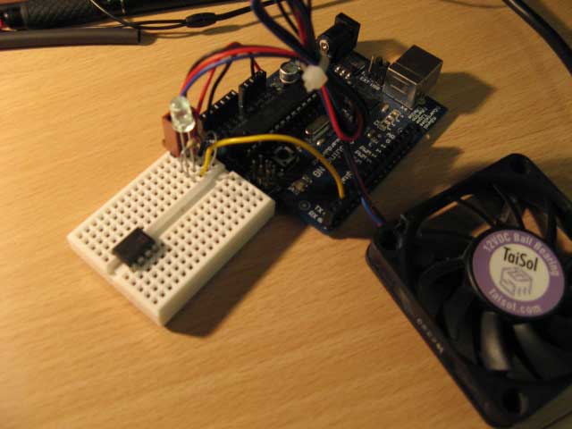
The hall effect sensor pin goes to pin 2, or interrupt 0. The LED and 10k resistor needed to be there for this to work. If your fan takes a lot of current, you might need to use an external power source.
Simple Circuit Option:
If the internal pull-up resistor for pin 2 (interrupt 0) is enabled by adding the line:
digitalWrite(2, HIGH);
to setup(), then the hall effect sensor can be connected directly to pin 2 without requiring an external 10k pull-up resistor and LED. The LED is actually only serving as a visual indicator in the original circuit and is not mandatory in for either.
Ze code:
//-----------------------------------------------
volatile byte rpmcount;
unsigned int rpm;
unsigned long timeold;
 void setup()
 {
   Serial.begin(9600);
   attachInterrupt(0, rpm_fun, RISING);
   rpmcount = 0;
   rpm = 0;
   timeold = 0;
 }
 void loop()
 {
   if (rpmcount >= 20) {
     //Update RPM every 20 counts, increase this for better RPM resolution,
     //decrease for faster update
     rpm = 30*1000/(millis() - timeold)*rpmcount;
     timeold = millis();
     rpmcount = 0;
     Serial.println(rpm,DEC);
   }
 }
 void rpm_fun()
 {
   rpmcount++;
   //Each rotation, this interrupt function is run twice
 }
//-----------------------------------------------
Plot of RPM over time:
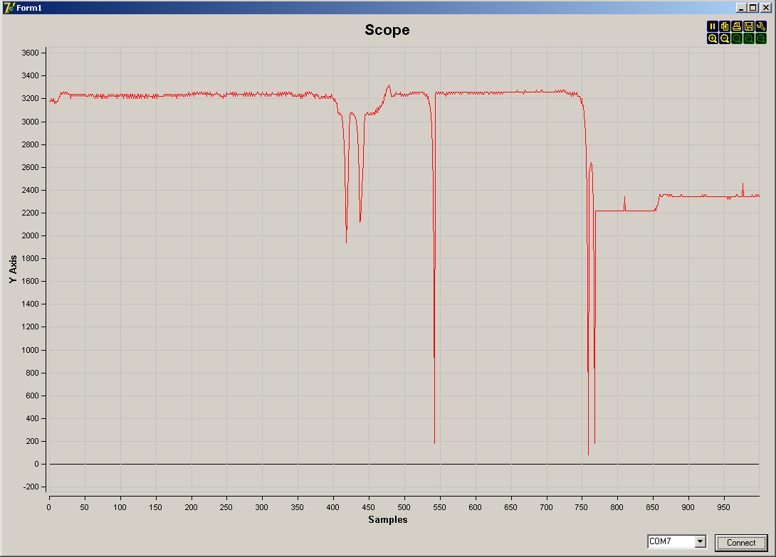
(right click -> "view image" to see the larger picture)
by zitron